
Summary
Full planning permission granted for a new build home to replace an existing dwelling.
The Brief
Space: to provide a modern open-plan living environment with clear circulation and maximising daylight.
Functions: 6 bedrooms with 4 ensuites; feature staircase; open-plan kitchen/dining/lounge area; utility room; pantry; sitting room; living room; garage; external landscape design.
Overview
Full planning permission has been obtained to replace the existing house with a larger property more suitable for modern family living.
In this project we began by designing for a full refurbishment and extensions to the existing house. Over time our client’s requirements changed and it became clear that demolition of the existing house would provide the most cost effective solution.
We work closely with you to ensure your specific requirements are included. As the design layouts evolve we will have regular meetings and make changes with you until the floor plans are agreed.
Every project is different and we do not provide generic solutions for problems.
Often there are specific planning and site constraints and we will ensure that these are taken into consideration during the design process.

Concept and Design
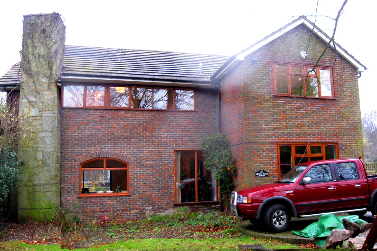
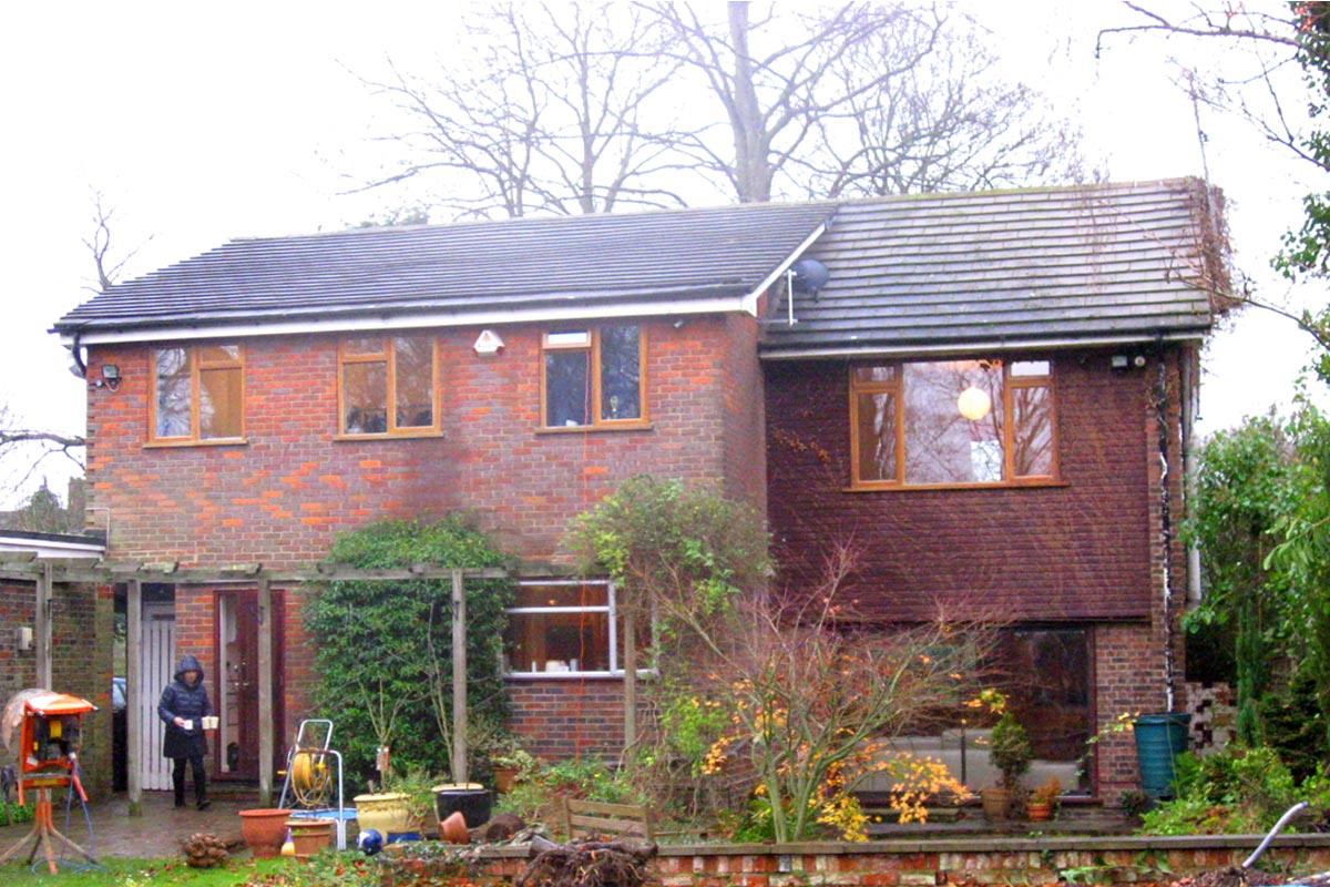
Left: photograph of existing front elevation as seen from the public footpath.
Right: photograph of existing rear elevation viewed from the garden.
"We’ll take the time to listen to your vision and then deliver it."
"We’ll take the time to listen to your vision and then deliver it."
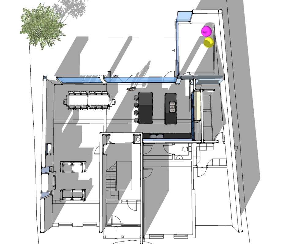
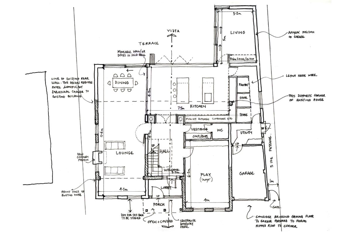
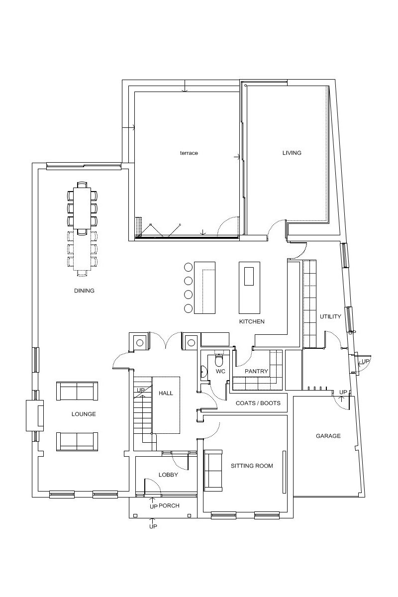
This early design layout provides clarity of circulation. The main entrance is relocated to the front of the house. A large hallway is created that is open to the underside of the roof where a wide skylight brings daylight into the centre of the home.
A vista through to the rear garden extends the feeling of space and connection to outside. The position of the contemporary kitchen wall and units leads round to a rear living area that opens up on to the garden terrace on two sides.
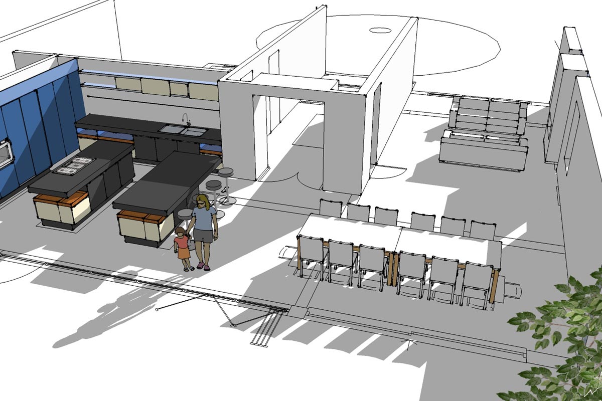
3D Computer Model
3D computer modelling is a service available for all our clients if required. We will sit with you in your home and the project can then be viewed together from any angle, both inside and out.
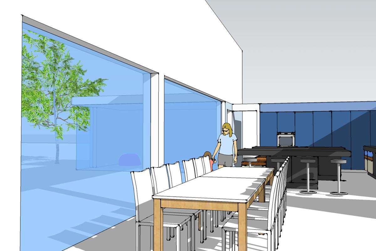
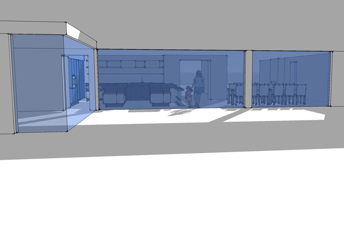
3D Computer Views
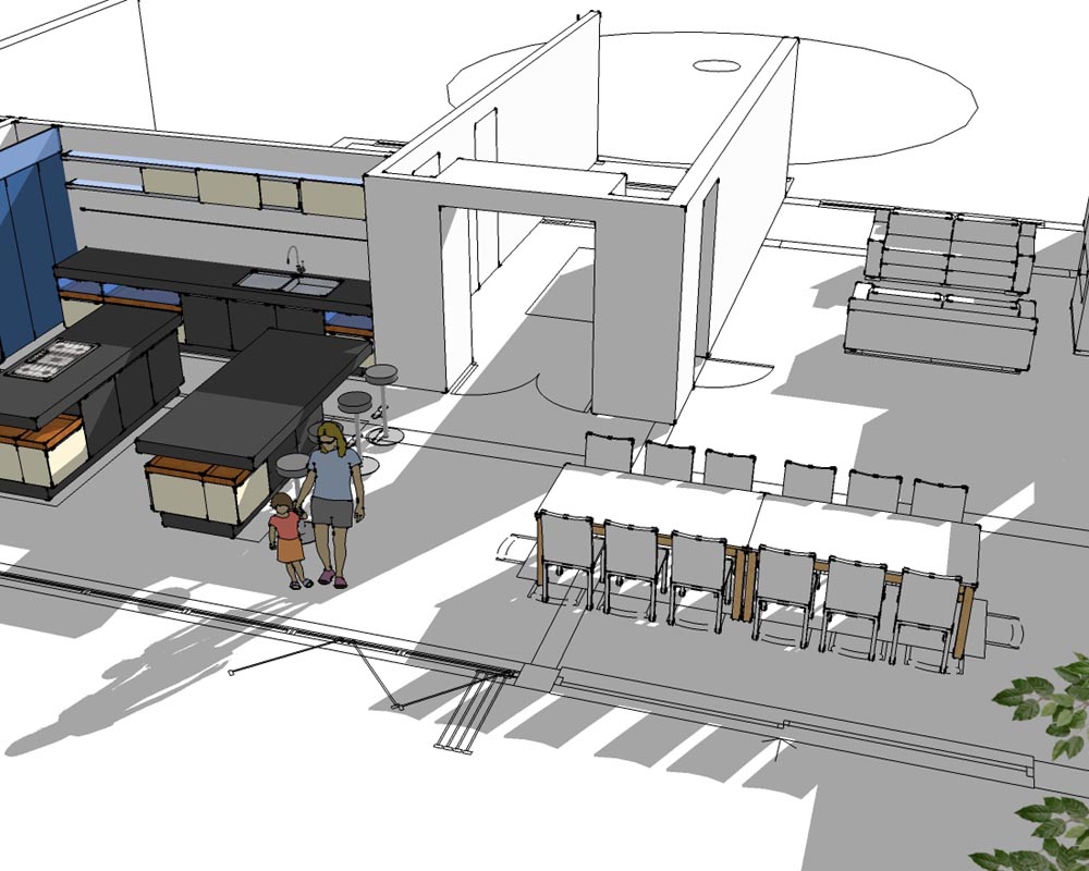
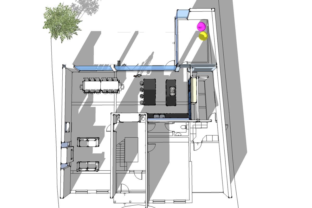
Left: view of kitchen from dining area.
Right: view of kitchen from rear garden
"We provide contemporary design solutions that are both simple and elegant."
"We provide contemporary design solutions that are both simple and elegant."
A 3D computer view of the kitchen / dining / sitting area from the rear garden with the rear wall removed for clarity.
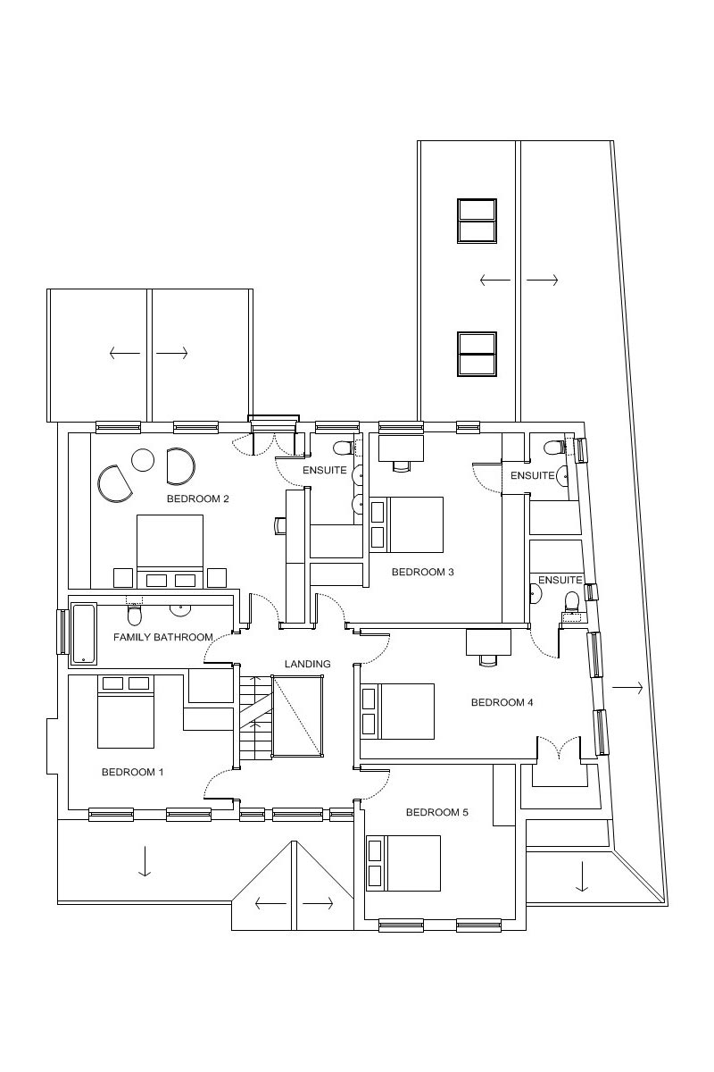
Ground and first floor plans
Left: ground floor plan.
Right: first floor plan.
Materials and Finishes
Left: proprietary external render system.
Right: stone paving to front drive and footpaths.

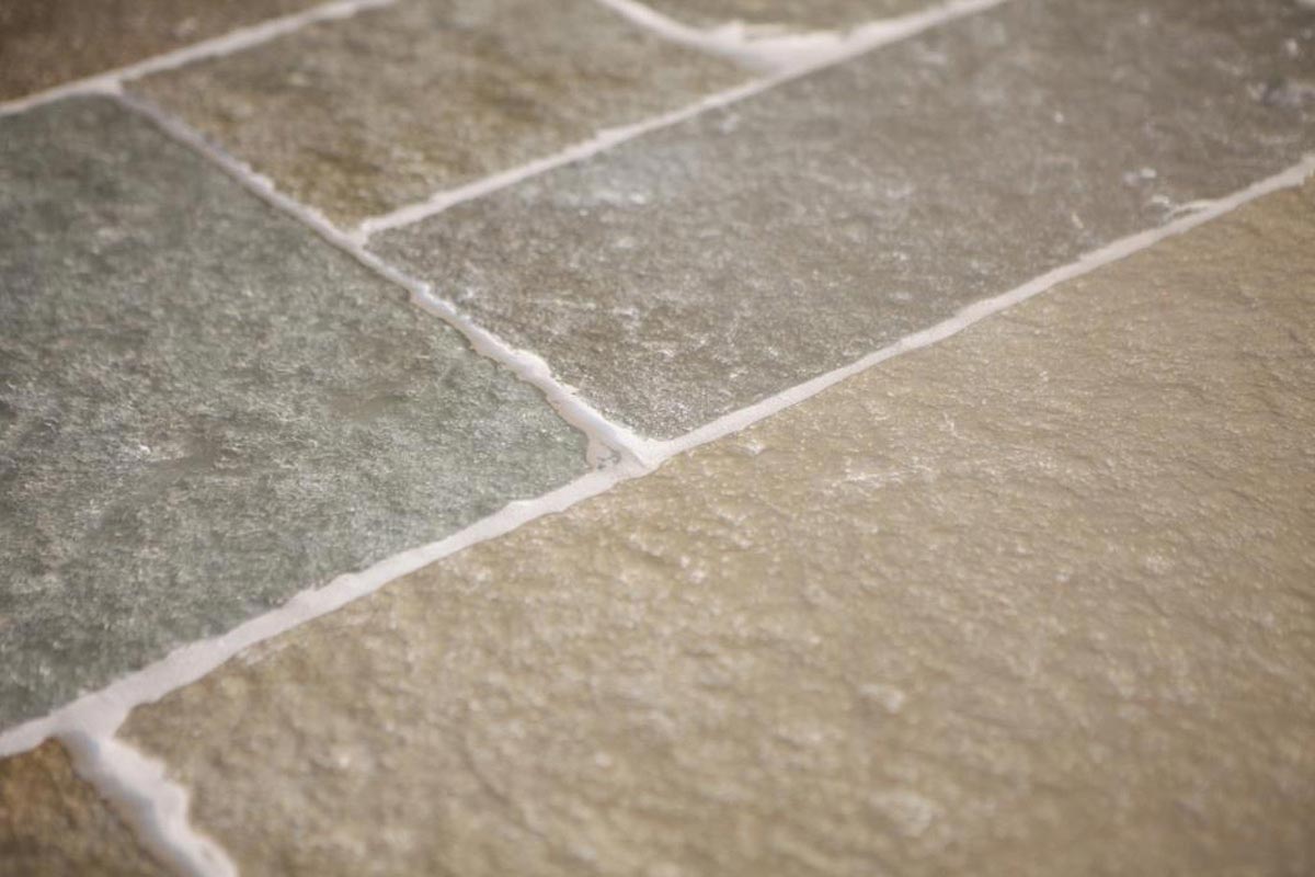
"Samples are obtained for the main building finishes."
"Samples are obtained for the main building finishes."
Handmade facing brick with a mortar colour to compliment the render used elsewhere.

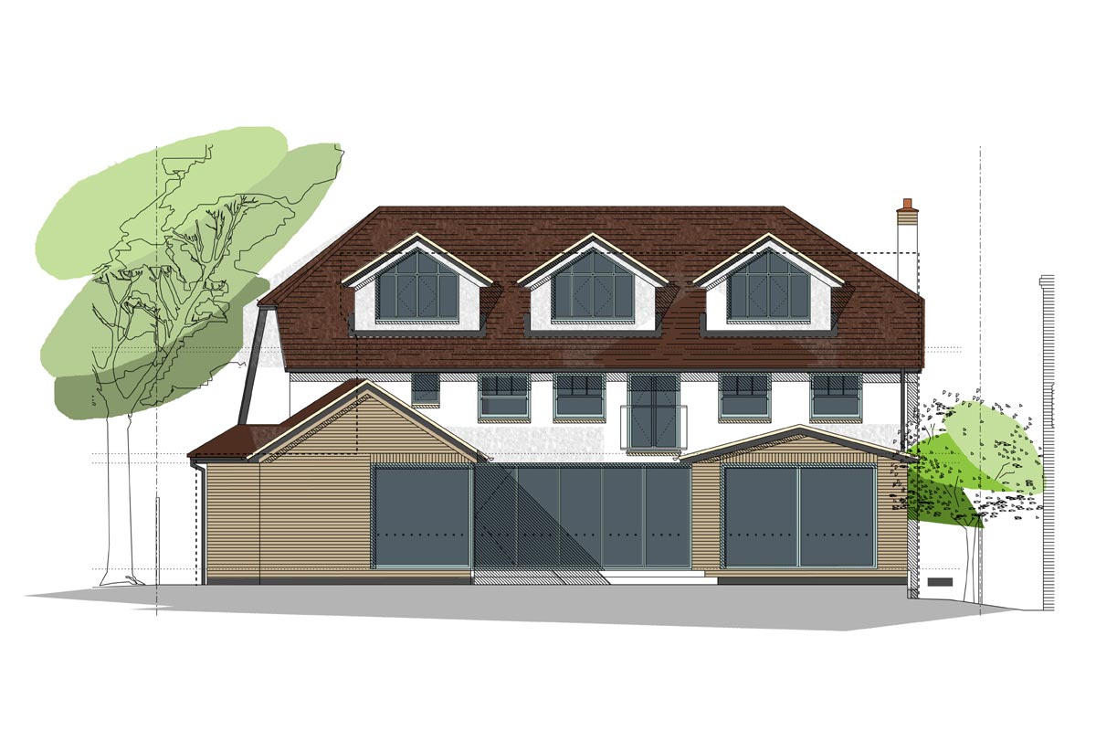
External Elevations
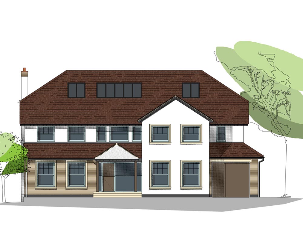
Left: front elevation.
Right: side elevation.
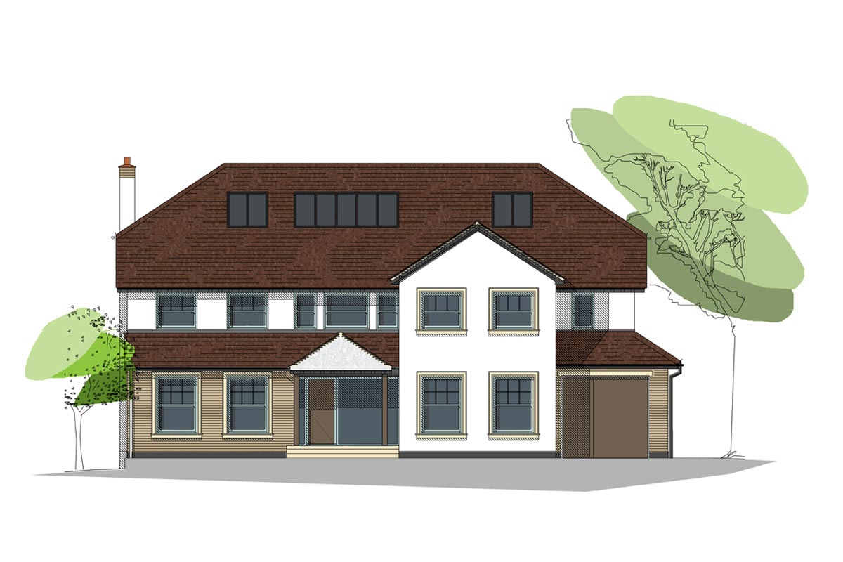
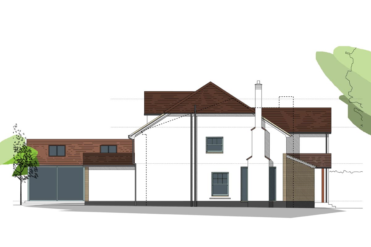
"Coloured presentation drawings indicate where materials are proposed."
"Coloured presentation drawings indicate where materials are proposed."
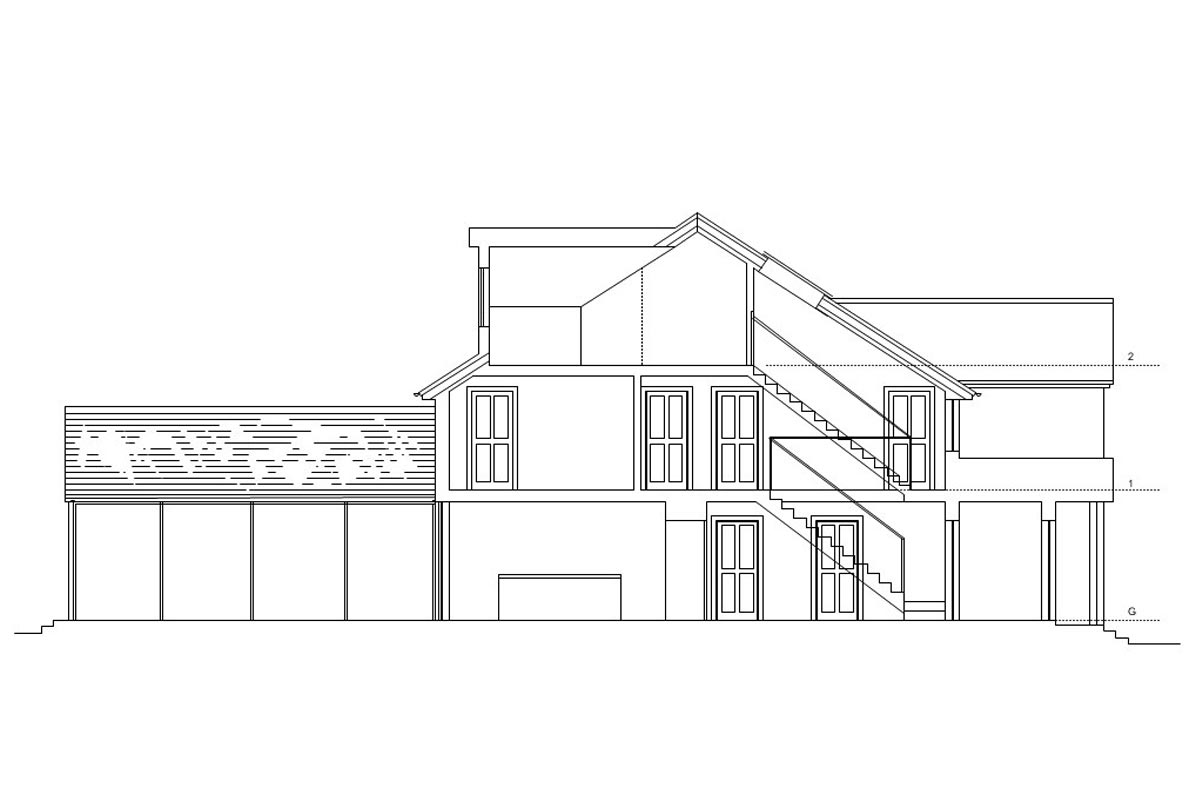
Rear elevation.
Attention to Detail
Our construction drawings are very detailed. We believe in drawing and specifying as much as possible so that we, you and the contractor know what is expected before the project construction work commences.
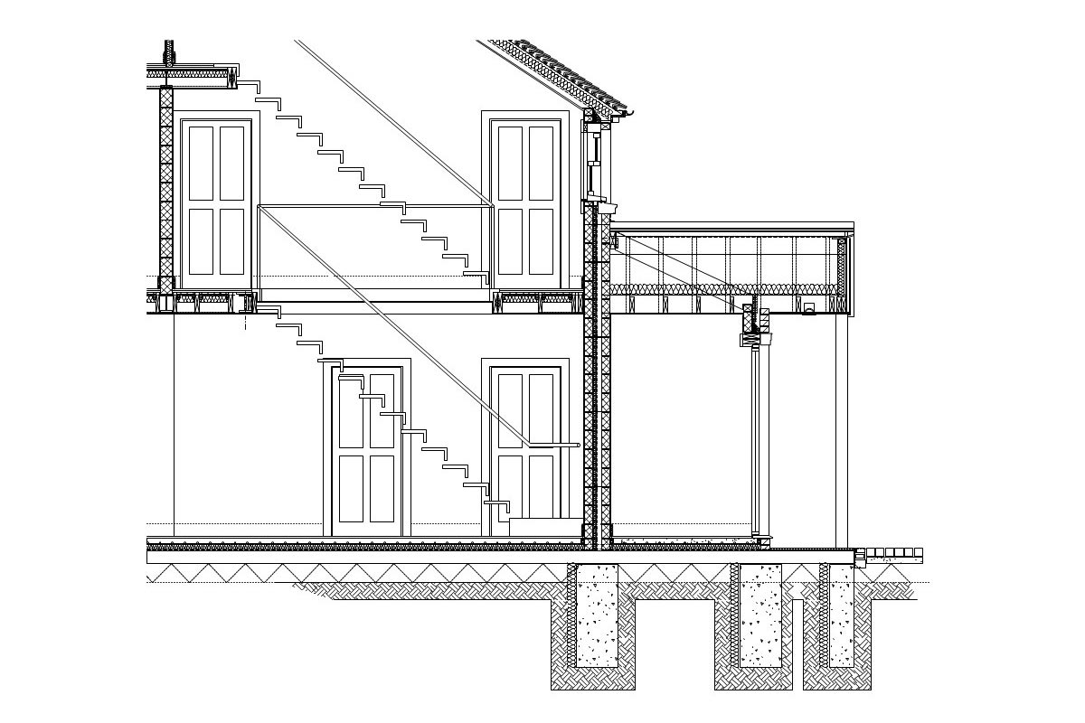
Getting closer….(1:20)
This image is the same section seen more closely.
Here the relationship of the main floor and wall construction can be seen.
If items are not clear at tender stage then there may be a dispute over what the contractor has priced for that is different from what you thought you were getting, ultimately leaving you with an additional bill to pay.
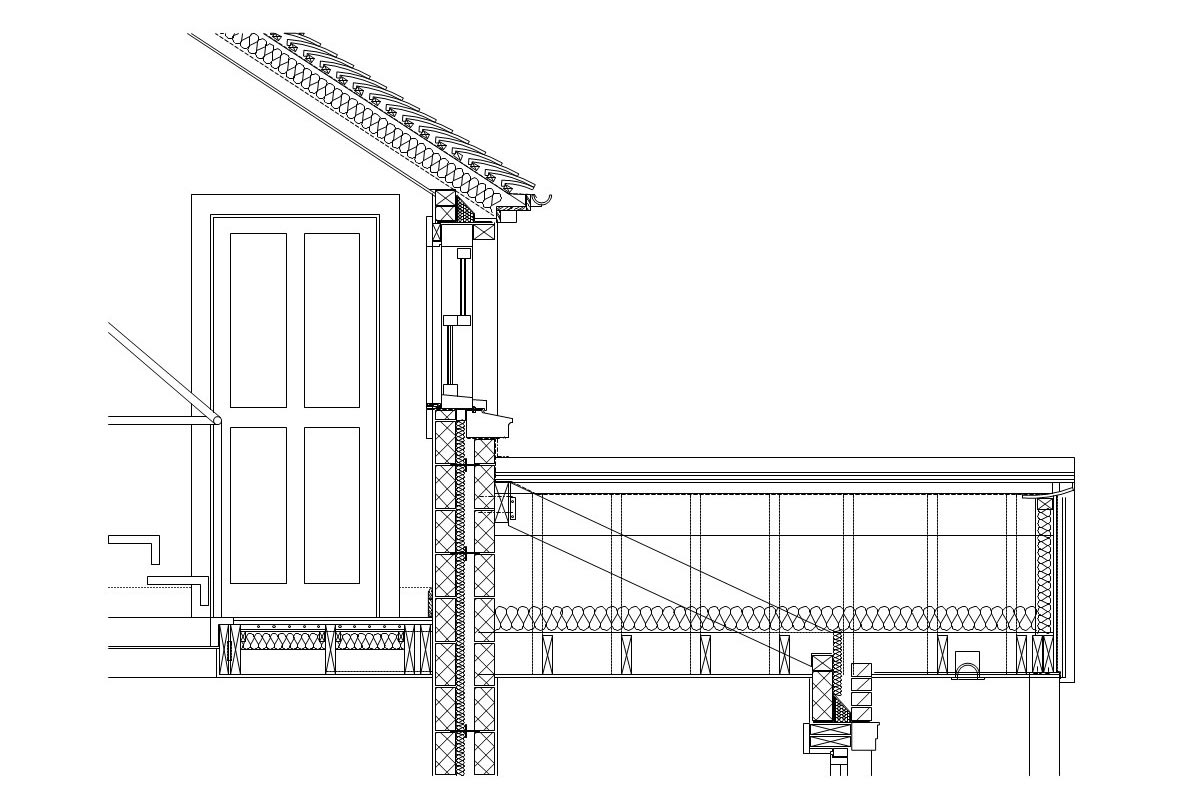
….and closer….(1:10)
At this scale the various individual components can be seen. By drawing the various elements to scale we know that they will fit together on site. If they don’t work on the ‘drawing board’ they won’t work during construction.
Some architects and technicians do not offer this level of service and instead they put the obligation onto your contractor to work these issues out on site. We would recommend that you check with the consultants you may be considering to understand what they offer for the fees that they are charging prior to appointment.
What initially may seem a higher design fee may actually represent a large cost and time saving when you think about the complexity of your project.
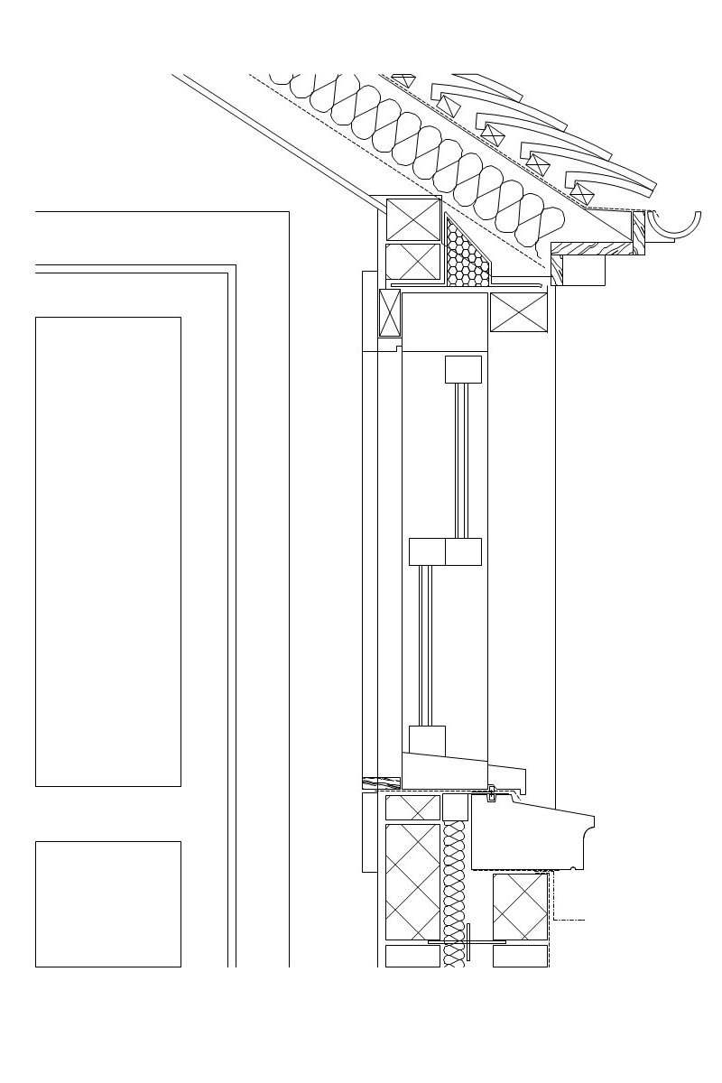
….and closer (1:5)
At this scale the relationship between the first floor hardwood sash windows; reconstituted stone cills and roof construction is clearly shown. This drawing was issued with the tender documentation and included many critical setting out dimensions and construction notes.
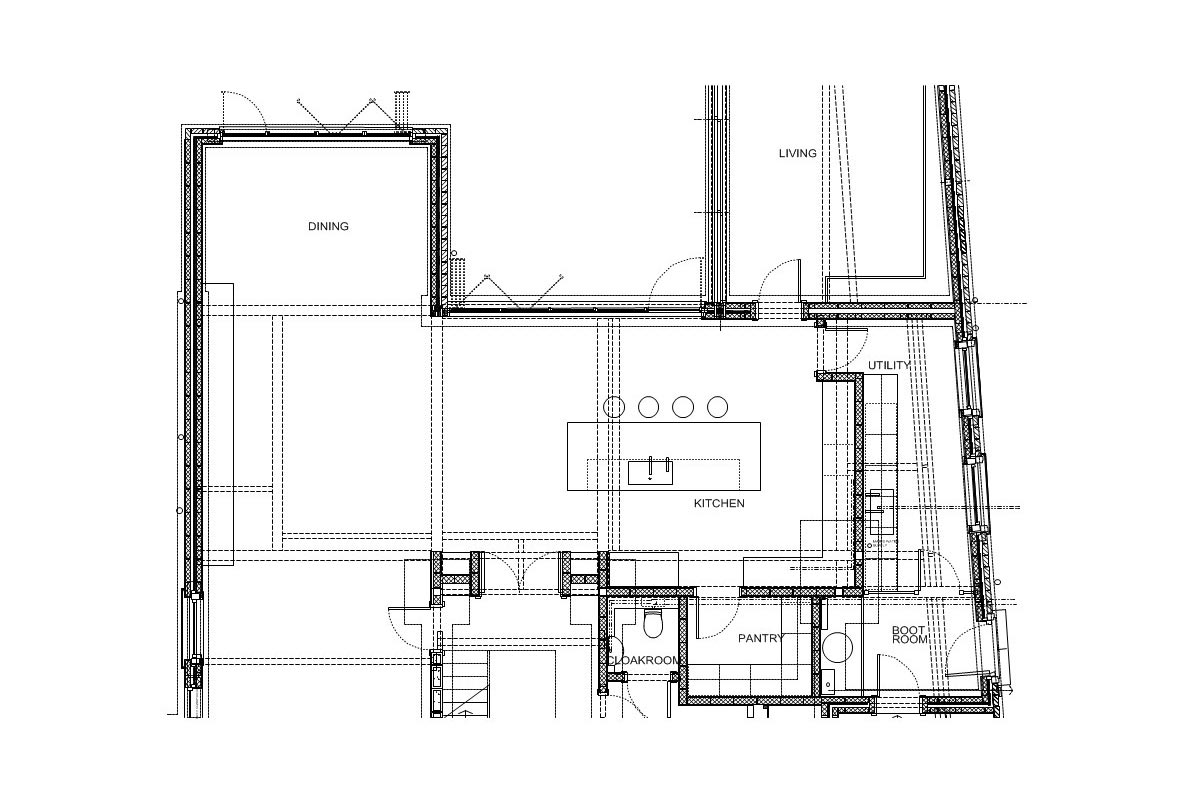
Construction Plan (1:50)
This is part of the ground floor plan.
All structural steel beams and columns are shown at the right scale and these are positioned so that they are concealed within walls and ceilings to ensure the completed project looks clean and well thought out.
We also produce 1:50 plans for the electrics; central heating and foul waste routes.
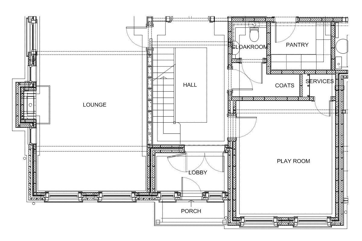
Construction Plan (1:20)
The 1:20 construction plans relate to the 1:20 construction sections and include numerous critical setting out dimensions and notes. The blockwork walls; window and door openings are set out to block dimensions to reduce cutting on site and simplify the construction stage.
The doors and windows on this drawing are based upon real door/window and frame sizes and this approach helps ensure that the architraves will fit and the window cills and frames work with the reconstituted stone cills and lintels above.
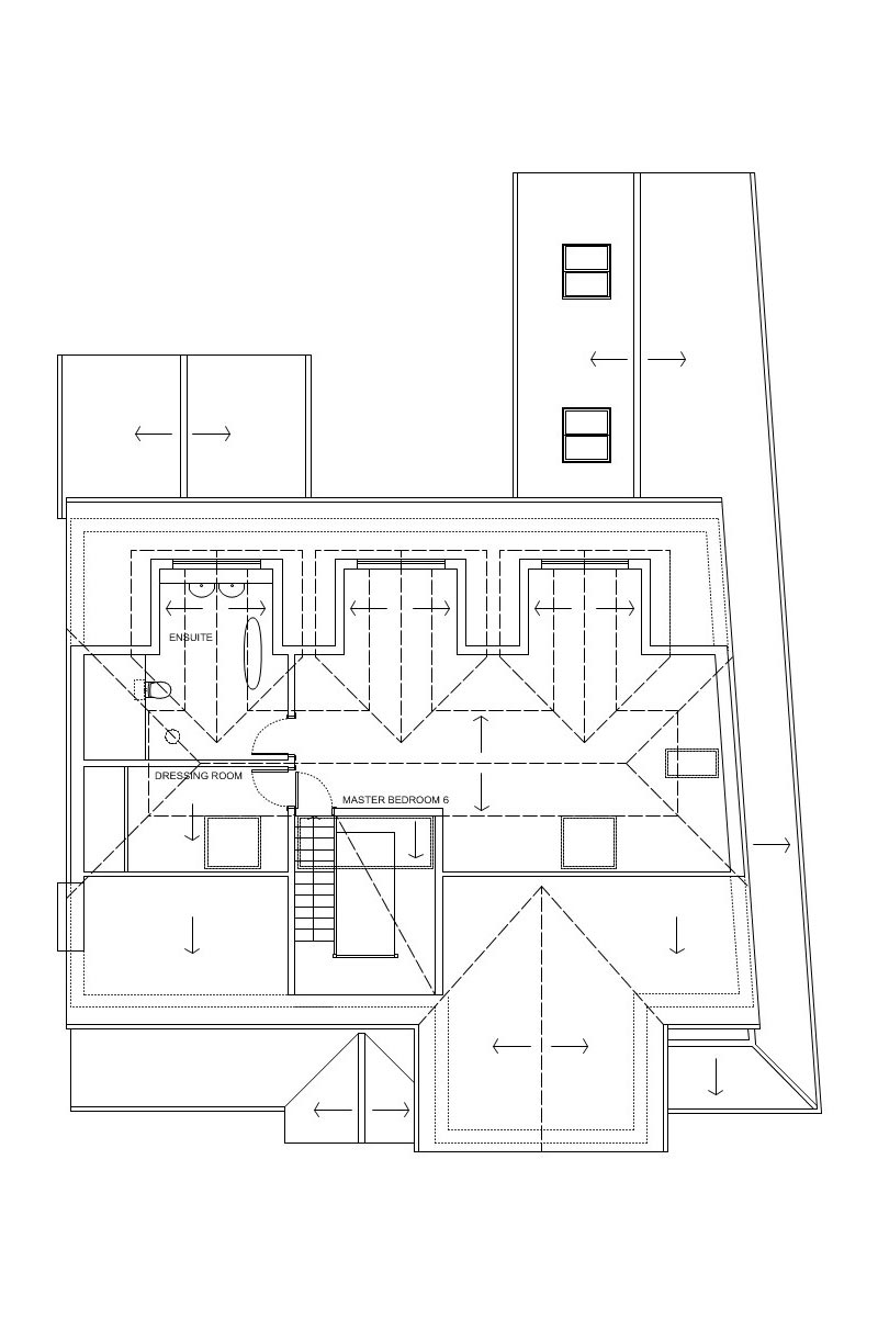
Second floor plan
Layout of second floor master bedroom; dressing room and ensuite bathroom.